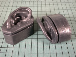
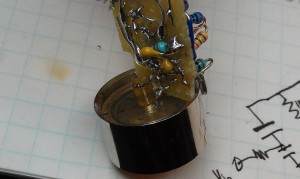
Putting “Real” mics in silicone ears
The holy grail of binaural audio for me has been to effectively interface a non-electret condenser capsule to an anatomically correct ear and ear canal. The simple mechanics limit the size of the diaphragms that could be used. An actual eardrum is on the order of 5mm.
My suspicion is that a “real” condenser element would provide the best possible signal to noise ratio. High frequency transient response would certainly suffer (compared to the electret mic) do to the the physics of a higher mass in the diaphragm. This would certainly be a worth-while price to pay for less self-noise in a microphone system. The Panasonic WM-61A electret (the Gold standard in DIY audio) has pretty poor noise performance (62dB S/N ratio @ 94dB SPL) when compared to “real” condensers. A human ear canal is on the order of 7mm so, connecting any practical condenser capsule to an accurate replica of it would result in a potentially un-natural resonance or impedance discontinuity in the interface.
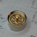
After I had satisfied myself that electret capsules in my generation-one silicone ear modules actually did the “binaural thing” effectively, I started looking at options for real condenser capsules. My initial experiments were with 20mm omnidirectional capsules that are designed to thread onto “pencil” condenser mics. I found a pair of capsules on Ebay for $45. They are not marked or branded, so I have no idea who actually made them. They have a gold plated mylar diaphragm in a brass housing. They thread onto (and work well on) a pair of Joe Meek JM27’s that I have. The measured capacitance is 45pF.
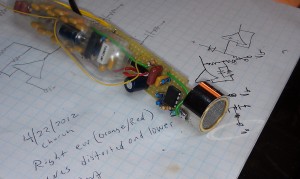
Another suspicion of mine is that there is an opportunity for greater S/N ratio to be achieved with a condenser mic by changing the circuit topology slightly and increasing the bias voltage (assuming the diaphragm could handle the electrostatic force and arcing was not a problem). Figure 1 is the basic circuit. This is a departure from the traditional high-voltage condenser preamp topology on two fronts.
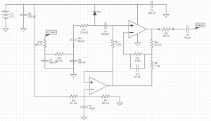 Primarily, it puts the condenser capsule in series between the the HV supply and the input of the initial gain stage. Also, it uses a jFET input opamp instead of the traditional class “A” configuration with a discrete N-channel jFET in source-follower mode. My first prototype circuit was with the MCP6022 by Microchip. The AD823 by Analog Devices will likely be the final choice. I can already hear the howling, crying and trash-talk from the guys that listen to vinyl and pay big bucks for oxygen-free wire. Here is my response: Compare the noise and distortion specs between your vintage jFET of choice and any modern jFET input opamp that is intended for low noise sensor applications. Further more, it is naive to think that a single jFET in a simple class A configuration could rival what is happening inside an opamp.
An obvious problem in this configuration is that it floats the body of the capsule at the bias voltage. In a traditional configuration, the body is at ground and becomes part of the noise shielding for the system. Having the capsule inside a dummy head protects it from being touched. (Protecting the toucher is probably a better way to express that.) The shielding concern is addressed by capacitor C6. It provides a relatively low AC impedance ground path for the body of the capsule.
The circuit uses an active ground (rail-splitter) to provide low impedance, half-scale virtual ground reference. This is a personal preference of mine over passive rail splits. Opamps also tend to come in dual packages, so there would tend to be a spare amp available. The low-pass filter formed by R6,R7 and C8 has a corner frequency of about 1.6Hz. More capacitance here would be fine/desirable. An additional small ceramic cap in parallel with C8 (.1uF, etc) would be reasonable if C8 were much larger or of an electrolytic type.
R1 and D1 are about protecting the input of the opamp in the event of an arc across the capsule. In the traditional configuration, the “top” terminal of the capsule would drop to ground potential in the event of an arc. In this configuration, an arc would deliver bias voltage (with the full faith and credit of C8) into the opamp input. Arcs have the potential to achieve outrageously high currents with rise times on the order of a few nano seconds. To limit the rise time, a low-pass filter is formed between R1 and the input capacitance of D1 and the opamp input. The total capacitance between them is on the order of 4 pF. The RC time constant is therefore on the order of 13nS. Modern schottky diodes have response times in the 1nS range. The concept here is to retard an arc transient long enough for the diode to transition out of reverse bias mode and shunt the current to the Vcc rail. The risk or arcing, I suspect, is not generally on the minds of preamp designers. The reason it’s on my mind is that I am interested in running the capsule at two or three times the typical bias voltage. I suspect (and plan to experimentally prove at some point) that there is “low-hanging fruit” (in terms of S/N ratio) to be picked by simply dialing up the bias voltage. The tradition phantom powered mic is drawing on its 48V source with a about a 3400 ohm source resistance. So in order to actually use any of the power delivered from the audio console, the available voltage needed to bias the capsule is reduced. For example in those JM27’s I have, the bias voltage is about 30V. My guess is that a tripling of the bias up to 100V would yield a 10dB improvement in S/N ratio – without making any changes in the preamp design. The 48V limit on professional audio equipment is likely a function of safety an UL rules. Anything up to 48V is considered “low voltage wiring” and falls under its own (lenient) set of rules. This is why telephone lines are based around 48V.
This brings us to the most significant aspect of the circuit. It is the combination of R3 and C3 in the feedback path. R3’s purpose should be obvious – it is to match the DC bias path between the inverting and non-inverting inputs. This will minimize the offset voltage that is due to bias currents. This is something any first year electronic student knows. C3 is the part that may be a new concept. It certainly was to me. I read an Analog Devices application note about noise in capacitive sensor preamps. They suggested that the AC bias path should be balanced too. Huh? That was a new on on me. I wanted to call up Old Dominion University and ask for a refund. So what I have in this circuit is R2||Mic on one input and R3||C3 on the other. The circuit still functions a traditional follower with a voltage gain of 21 (26.4dB). C3 does not contribute to an integrator-type response (LPF) like you may think at first glance.
My prototype circuit did not employ the protection diode. Consequently, I destroyed two opamps in a row by careless handling of the circuit. Having 100V I extremely close proximity to the unprotected inputs of an opamp is asking for it. The 100V source I’m referring is colpits oscillator (LC) driving a seven stage diode-capacitor multiplier ladder. The oscillator runs at about 250KHz. Its quiescent current is 4.5mA on a 9V battery, and delivers 100VDC (unloaded).

